

A place for general chat about the Jimny. Please make sure you post in the correct section on the site, this way it keeps the site tidy AND ensures you get a more relevant answer.
Suppliers/Dealers or anyone selling with a commercial view in mind CANNOT post here unless responding to a specific request of a member in a "wanted" post.
Suppliers include people "breaking for spares" on a regular basis, when purchasing spares members should ask a supplier what they contribute to the running of the forum particularly if contacted by a Private Message
Suppliers or Members who have contributed to the forum can be identifed by the
 logo.
logo.
Suppliers/Dealers or anyone selling with a commercial view in mind CANNOT post here unless responding to a specific request of a member in a "wanted" post.
Suppliers include people "breaking for spares" on a regular basis, when purchasing spares members should ask a supplier what they contribute to the running of the forum particularly if contacted by a Private Message
Suppliers or Members who have contributed to the forum can be identifed by the
TPMS
Less
More
- Posts: 2328
- Thank you received: 664
26 Mar 2026 16:39 #264124
by DrRobin
2020 blue SZ5 (one of the last to be registered in the UK)
Ex 2011 Blue Jimny SZ4
Northumberland Jimny Blog
The Jimny must have an antenna for the TPMS, but as far as I can tell the TPMS module just has wires coming away from it, so either the antenna is integral to the module or it’s just picked up by one of the wires.
Either way I am going to try the SpoofTPMS near the driver’s footwell next time I have my off-road wheels on.
To be honest, I only have the off-road wheels on for a couple of days at a time and the loss of the display isn’t a problem when in the actual trial.
Either way I am going to try the SpoofTPMS near the driver’s footwell next time I have my off-road wheels on.
To be honest, I only have the off-road wheels on for a couple of days at a time and the loss of the display isn’t a problem when in the actual trial.
2020 blue SZ5 (one of the last to be registered in the UK)
Ex 2011 Blue Jimny SZ4
Northumberland Jimny Blog
Please Log in or Create an account to join the conversation.
26 Mar 2026 20:21 - 26 Mar 2026 20:29 #264127
by mlines
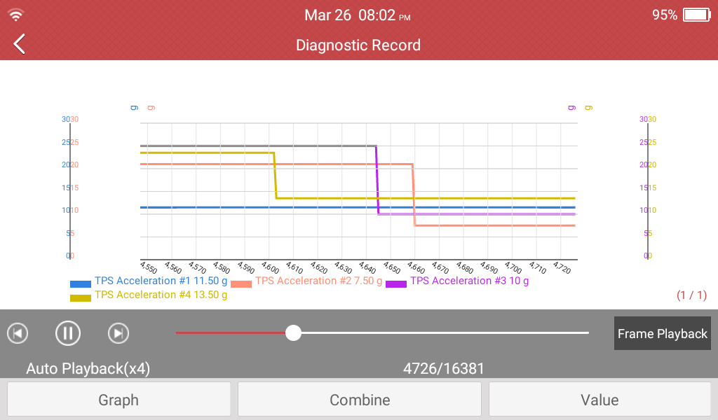

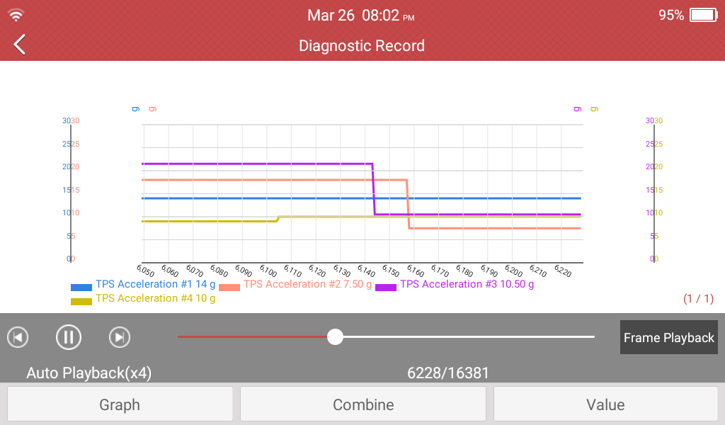
So I connected my reader to the TPMS module last night.
It detected the module and could read the values being sent to it by the sensors.
One of the value it could read was the accelerometers, which matches up with what Suzuki talks about in the manual.
In the pictures with a blue jagged line curving up and down that is the road speed of the car.
The other four lines are the accelerometers built into the TPMS sensors.. the pictures show these moving around across a range of values and also moving separately which you would expect. . As it was a local drive they are all over the place , so I don't think it proves things either way but it shows they are reading more than an on/off movement and are also reporting their readings to the TPMS module. I guess I need to get more scientific and record the car going in circles. I probably need to compare the readings with the abs sensor pulses.

Martin
2003 M13 early KAP build.
3" Trailmaster lift with 1.5 Spacers on front
Customised winch bumper and roll cage
235/85R16 Maxxis Bighorns on 16" Rims, 4:1 Rocklobster, Rear ARB locker and on-board air
Corrected arms all-round, rear disks, Recaro seats and harnesses
So I connected my reader to the TPMS module last night.
It detected the module and could read the values being sent to it by the sensors.
One of the value it could read was the accelerometers, which matches up with what Suzuki talks about in the manual.
In the pictures with a blue jagged line curving up and down that is the road speed of the car.
The other four lines are the accelerometers built into the TPMS sensors.. the pictures show these moving around across a range of values and also moving separately which you would expect. . As it was a local drive they are all over the place , so I don't think it proves things either way but it shows they are reading more than an on/off movement and are also reporting their readings to the TPMS module. I guess I need to get more scientific and record the car going in circles. I probably need to compare the readings with the abs sensor pulses.
Martin
2003 M13 early KAP build.
3" Trailmaster lift with 1.5 Spacers on front
Customised winch bumper and roll cage
235/85R16 Maxxis Bighorns on 16" Rims, 4:1 Rocklobster, Rear ARB locker and on-board air
Corrected arms all-round, rear disks, Recaro seats and harnesses
Last edit: 26 Mar 2026 20:29 by mlines.
Please Log in or Create an account to join the conversation.
27 Mar 2026 11:20 - 27 Mar 2026 15:41 #264133
by Motacilla
Will be interesting to hear your results from moving the spoof unit. You may wish to let the maker (I forget his name at the moment) know that the Jimny's TPMS module location might require his installation instructions to be slightly rewritten!
Correct, just to be clear, when we are talking about the TPMS "antenna" or "module" here, we are talking about a single device. It is a small computer/control unit, incorporating an antenna internally, which connects to the CANbus.The Jimny must have an antenna for the TPMS, but as far as I can tell the TPMS module just has wires coming away from it, so either the antenna is integral to the module or it’s just picked up by one of the wires.
Will be interesting to hear your results from moving the spoof unit. You may wish to let the maker (I forget his name at the moment) know that the Jimny's TPMS module location might require his installation instructions to be slightly rewritten!
Last edit: 27 Mar 2026 15:41 by Motacilla.
Please Log in or Create an account to join the conversation.
27 Mar 2026 11:36 - 27 Mar 2026 11:49 #264134
by Motacilla
Super interesting, thanks! I have some questions about what we are looking at in the screenshots. Questions in bold font below.
Really interesting data, thanks again!So I connected my reader to the TPMS module last night.
Can you explain further? What kind of reader is this, how is it connected to the TPMS module?
so I don't think it proves things either way but it shows they are reading more than an on/off movement and are also reporting their readings to the TPMS module.
Yes, more granular than I expected, very interesting data. But you seem to be showing continuous data, or perhaps I am not understanding what is shown in the screenshots, specifically the X axis. Perhaps it is just the way the tool creates graphs.
I guess I need to get more scientific and record the car going in circles. I probably need to compare the readings with the abs sensor pulses.
An easier test would be simply to move the TPMS receiver from the right-front to the left-rear of the vehicle with an extension cable, and see if the location values change. Well, theoretically easier -- one would have to fab a cable of course.
If this is CANbus data, how is it being put to the bus by the TPMS module? Is all of the tyre inflation data contained in a single packet in an ordered list, or are you saying that the CANbus information is several packets containing all of the data coming off of the sensors? I'm not clear on whether this is only data going into the TPMS module (i.e. as received) or coming out of the module to the CAN.
I guess I need to get more scientific and record the car going in circles.
More interesting I think would be the car going in a straight line at the moment of the first sensor pulse.
Last edit: 27 Mar 2026 11:49 by Motacilla.
Please Log in or Create an account to join the conversation.
27 Mar 2026 13:11 - 27 Mar 2026 13:11 #264135
by mlines
Martin
2003 M13 early KAP build.
3" Trailmaster lift with 1.5 Spacers on front
Customised winch bumper and roll cage
235/85R16 Maxxis Bighorns on 16" Rims, 4:1 Rocklobster, Rear ARB locker and on-board air
Corrected arms all-round, rear disks, Recaro seats and harnesses
The tool is a Launch CREADER CRP919X. It is what I would call an entry level professional tool. This is the wired version which is currently around £245. There is a Lite version which is around £20 cheaper but is too restricted and there is a Bluetooth version for £300+.
Its a bi-directional tool so it can command devices to report or operate which is perhaps what makes it professional.
However, as it is at the low end, there are some limitations. Principally for me the one limitation is no data export. So you can look at the data on the tool and send data reports to people to see but there is no official raw data export capability to other devices for further analysis.
It connects to the car OBDII port and hence can see and interact with the canbus through the Suzuki Gateway module.
So in the pictures you are seeing it connected to the OBDII port and then the software on it has a session set up to the TPMS controller that is sitting on the CANBUS. Once it has established communication with the controller you are presented with a list of parameters available to monitor or control. What is shown on the graph is the data answer that was requested by the monitor from the TPMS controller. I requested data from 4 sensors simultaneously.
You can then look at these simply in real time or record them for analysis over time.
This real time data collection is via a polling mechanism. In the pictures the X-axis is marked at 10 second intervals and the Y axis is in "g" which I think means g as in gravity but at one point the device suggested it was "grams" which seems wrong. I also think that as it is an accelerometer it should only report "change".
Looking at the polling it looks like 1 second intervals so changes that are less than 1 second will appear as a step change. But there is also the "polling" that the TPMS controller has internally with the sensors which, as you say, are low power so they need to only send as fast as is needed to function whilst saving power. I think that is why the combination of the monitoring tool polling and the TPMS controller receiving sensor updates at an unknown rate makes the wave forms more square. I undestand that some TPMS sensors generate power through the rotation of the wheels so perhaps the load on their little batteries only occurs when stationary.
My concern with the graphs is that the scales are automatic, you have no control over the scaling and also dynamic re-scaling occurs which causes visual jumps in the live display (although these are not visible in the recording)
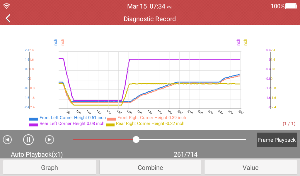
Below is a view of a continous record of a different type of sensor. This is are the suspension height sensors on my Range Rover as I drive the silky smooth roads of Wokingham

Its a bi-directional tool so it can command devices to report or operate which is perhaps what makes it professional.
However, as it is at the low end, there are some limitations. Principally for me the one limitation is no data export. So you can look at the data on the tool and send data reports to people to see but there is no official raw data export capability to other devices for further analysis.
It connects to the car OBDII port and hence can see and interact with the canbus through the Suzuki Gateway module.
So in the pictures you are seeing it connected to the OBDII port and then the software on it has a session set up to the TPMS controller that is sitting on the CANBUS. Once it has established communication with the controller you are presented with a list of parameters available to monitor or control. What is shown on the graph is the data answer that was requested by the monitor from the TPMS controller. I requested data from 4 sensors simultaneously.
You can then look at these simply in real time or record them for analysis over time.
This real time data collection is via a polling mechanism. In the pictures the X-axis is marked at 10 second intervals and the Y axis is in "g" which I think means g as in gravity but at one point the device suggested it was "grams" which seems wrong. I also think that as it is an accelerometer it should only report "change".
Looking at the polling it looks like 1 second intervals so changes that are less than 1 second will appear as a step change. But there is also the "polling" that the TPMS controller has internally with the sensors which, as you say, are low power so they need to only send as fast as is needed to function whilst saving power. I think that is why the combination of the monitoring tool polling and the TPMS controller receiving sensor updates at an unknown rate makes the wave forms more square. I undestand that some TPMS sensors generate power through the rotation of the wheels so perhaps the load on their little batteries only occurs when stationary.
My concern with the graphs is that the scales are automatic, you have no control over the scaling and also dynamic re-scaling occurs which causes visual jumps in the live display (although these are not visible in the recording)
Below is a view of a continous record of a different type of sensor. This is are the suspension height sensors on my Range Rover as I drive the silky smooth roads of Wokingham
Martin
2003 M13 early KAP build.
3" Trailmaster lift with 1.5 Spacers on front
Customised winch bumper and roll cage
235/85R16 Maxxis Bighorns on 16" Rims, 4:1 Rocklobster, Rear ARB locker and on-board air
Corrected arms all-round, rear disks, Recaro seats and harnesses
Last edit: 27 Mar 2026 13:11 by mlines.
Please Log in or Create an account to join the conversation.
27 Mar 2026 16:12 #264137
by Motacilla
More great info, thanks. If I can summarize the tool, it would be one that pulls the data from the control unit (in this case TPMS) through the gateway. In other words, full data stream, but not packet-by-packet CAN sniffing. I get it now, thanks.
The reason that I say the sensor transmission periodicity is a side point is that I believe the wheel position can't be redetermined continuously via wheel speed matching. Here is my logic: if the car matched the wheel speed (via ABS sensors / steering angle sensor) to the TPMS-reported accelerometer data continuously, that is, at each TPMS sensor broadcast or some other interval during driving.... then among other things a spoof box wouldn't work, because the spoof box cannot not spoof accurate accelerometer data.
So, in order for wheel-speed matching as you describe to work, I believe it has to happen only at an initialization point, and then position simply persists after that for the rest of the session, without being checked or changed. At least, that is how it would seem to me. (I still think there are other issues not addressed, and I still like my signal-gain position, but I'm loving the detailed information!)
If you accept that logic, then I think we focus on the question of what is happening at the initialization point, which would be just a minute or two, or perhaps as low as ~16 seconds of travel above the TPMS normal-operation wheel speed. And, what happens during error conditions, such as when a TPMS sensor transmits when the Jimny is driving straight ahead during initialization, or more generally, the reported wheel speed for a specific sensor's broadcast "snapshot" matches more than one wheel at that moment in time.
The data is really interesting, thanks again for posting.
(Of course, if we were really smart, we would just ask the clever fellow who made the spoof box to give us the answer... but where is the fun in that?)
Its a bi-directional tool so it can command devices to report or operate which is perhaps what makes it professional.
Just a side question out of curiosity, does it do the reprogramming tasks that the VDO tool does? Not useful if not running a tyre shop, but kind of fun to play with...
Looking at the polling it looks like 1 second intervals so changes that are less than 1 second will appear as a step change. But there is also the "polling" that the TPMS controller has internally with the sensors which, as you say, are low power so they need to only send as fast as is needed to function whilst saving power. I think that is why the combination of the monitoring tool polling and the TPMS controller receiving sensor updates at an unknown rate makes the wave forms more square. I undestand that some TPMS sensors generate power through the rotation of the wheels so perhaps the load on their little batteries only occurs when stationary.
Here is where I scratch my head a little at the output. The sensors are only transmitting at XX-second intervals, on the Jimny either 16- or 64-second schedules depending. So I'm not clear on how the system could have data any more granular than that.
That is kind of a side question to our main point, but it puzzles me.
Below is a view of a continous record of a different type of sensor. This is are the suspension height sensors on my Range Rover as I drive the silky smooth roads of Wokingham
This is why I depart from the broad public consensus that computers in cars are more trouble than they are worth. When you have the right tool, being able to see sensor outputs is like having X-ray vision, and it can make diagnosis so much easier. (Plus CANbus hacking can do fun things, like the Jimny door lock tricks from those Aliexpress units.)
The reason that I say the sensor transmission periodicity is a side point is that I believe the wheel position can't be redetermined continuously via wheel speed matching. Here is my logic: if the car matched the wheel speed (via ABS sensors / steering angle sensor) to the TPMS-reported accelerometer data continuously, that is, at each TPMS sensor broadcast or some other interval during driving.... then among other things a spoof box wouldn't work, because the spoof box cannot not spoof accurate accelerometer data.
So, in order for wheel-speed matching as you describe to work, I believe it has to happen only at an initialization point, and then position simply persists after that for the rest of the session, without being checked or changed. At least, that is how it would seem to me. (I still think there are other issues not addressed, and I still like my signal-gain position, but I'm loving the detailed information!)
If you accept that logic, then I think we focus on the question of what is happening at the initialization point, which would be just a minute or two, or perhaps as low as ~16 seconds of travel above the TPMS normal-operation wheel speed. And, what happens during error conditions, such as when a TPMS sensor transmits when the Jimny is driving straight ahead during initialization, or more generally, the reported wheel speed for a specific sensor's broadcast "snapshot" matches more than one wheel at that moment in time.
The data is really interesting, thanks again for posting.
(Of course, if we were really smart, we would just ask the clever fellow who made the spoof box to give us the answer... but where is the fun in that?)
Please Log in or Create an account to join the conversation.
Time to create page: 0.191 seconds