![]() The content of any article might be expanded / improved in the future - revisit it sometimes.
The content of any article might be expanded / improved in the future - revisit it sometimes.
![]() Seen a mistake? Know something that isn't written? Edit and change this article yourself!
Seen a mistake? Know something that isn't written? Edit and change this article yourself!
![]() Some images in the article (if present) can be enlarged by clicking on them.
Some images in the article (if present) can be enlarged by clicking on them.
Contents
Introduction
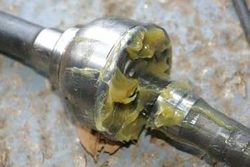
If you off-road a Jimny (or any of the Suzuki classic 4wd vehicles) then you may well end up changing a CV Joint. These are a weak point in the front axle and will break if you are heavy footed or have large tyres fitted.
It is also closely tied in with changing/working on the kingpin bearings so some of the steps are duplicated.
So what are the symptoms of worn/broken CV joints:
- Clicking when in 4WD when turning
- Banging and snatching of the steering wheel
- Loss of 4wd
CV joint information
Suzuki uses two different CV joints in the Jimny. One is straight forward to purchase on the parts market and the other is nearly impossible to source.
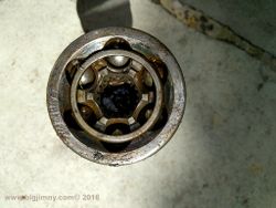
- Type 1: 6 balls, 26 external splines and 19 internal splines. - BigJimny Store NTN 75LAC CT9U)
- Type 2: 8 balls, 26 external splines and 29 internal splines. - BigJimny Store (possibly marked NTN EBJ82 although NTN call it an 8-Ball CV)
| Model | Balls | Inner Splines | Outer Splines | Outer Case Dia | Inner Case Dia | Shaft Dia |
|---|---|---|---|---|---|---|
| NTN BJ75LAC | 6 | 19 | 26 | 91.6mm | 72.6mm | 19.0mm |
| NTN EBJ82 | 8 | 29 | 26 | 91.6mm | 72.6mm | 21.2mm |
NTN 75LAC CV Joint
NTN 75LAC CV Joint
Changing the CV joint
Tools
- Standard metric sockets and spanners
- Assorted screwdrivers
- Circlip pliers (External)
- An E10 Torx socket for the Vacuum Hub Bolts
- A ball joint splitter
- 1" Imperial Socket
- G-Clamp or brake piston retractor
The Video
Before you read the guide below you may wish to view the video of changing the Kingpin bearings. This shows most of the steps for a CV joint so is a useful reference.
Removing the Caliper and pads
- First of all secure the car.
- Release the wheel nuts and jack up the car and remove the road wheel.
- This then reveals the brake caliper.
- The picture shows the passenger side (nearside) caliper (UK).
- Using a 12mm spanner, release the front caliper bolt (the left is the front of the car in this picture).
- Then loosen the same bolt on the rear of the caliper.
- The caliper then opens up using the rear bolt as a hinge.
- The pads are retained by small spring clips.
- A simple pull on the pads (horizontally away from the disk) should remove them.
- If the pads resist, gently prise out the pads with a small screwdriver - do not remove the spring clips).
- If you require new pads, spring clips or a caliper fitting kit then these are available in the BigJimny Store.
Removing the Brake Disc
- The caliper is held on with two bolts at the rear (see below).
- Release the bolts and tie the caliper to the spring to keep it out of the way.
- Now the front brake disc can be removed.
- If you are lucky it will simply pull off, but if you have problems then there are two M8 holes in the disk hub.
- Simply run two bolts into these holes and the disk will push off the hub.
- The picture shows a bolt being used to push the disk off the hub.
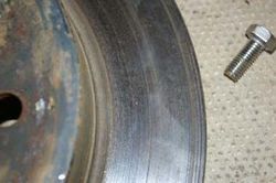
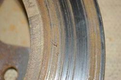
- My disk appeared to be ok on the visible side but the rear showed some bad wear so I will change them as part of this job.
- New disks are available in the BigJimny Store.
Dismantling the Hub
- Now the Freewheeling Hub needs to be removed.
- Suzuki have used Torx bolts to secure these so you will require an E10 socket to remove the bolts.
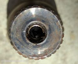
- With the hub removed, the driveshaft is exposed.
- The driveshaft is retained with a circlip, so use a pair of circlip pliers to remove it.
- This is really fiddly and can be an annoying task.
- Behind the circlip is a rectangular washer that should also be removed.
- Note that I have also marked with white paint the orientation of the freewheeling hub, this is not strictly needed.
- Gently pull the two vacuum hoses for the hub from the knuckle, making sure you note which one connects to each pipe.
- It is essential that you get this correct else the hub will not work again.
- Also note that if you have an ABS equipped vehicle then you will have to remove the sensor.
- I do not have photos of this but the video shows it.
![]() It is really easy to shear the ABS bolt! If you can, soak it for a couple of days previously in penetrating oil.
It is really easy to shear the ABS bolt! If you can, soak it for a couple of days previously in penetrating oil.
- At the rear of the hub, release the small bolts holding the seal and retainer.
- You can see that the swivel hub is covered in oil, a bad sign for KingPin problems.
- Undo the nuts on the steering joints.
- If the joint rotates, then put a jack under the joint and lift the car slightly to lock the joint.
- Using a splitter, split the steering joints (two to do on the passenger side and one on the drivers side – UK).
- Finally, release the KingPin bolts themselves.
- There are two sets, top and bottom and they must not be mixed.
- You can see in the picture that I have marked them up with a letter T.
- If you are doing both sides at once then do not mix them across either!.
- The KingPins are also held in with sticky sealant so you will need to prise them out.
- The hub will now pull off and the driveshaft can be removed.
- Depending on how broken the CV is, the shaft may come out in two pieces.
- The next stage is to CLEAN, CLEAN and then CLEAN again.
- Clean the swivels inside and out, clean the knuckles and make sure all broken CV parts are removed.
- The CV Joint is held on the driveshaft by a hidden C-Clip.
- The only way to dismantle a whole CV Joint (yours may already be in bits if you have really broken it!) is to drive the joint off with a hammer.
- Clamp the driveshaft into a vice and, holding the joint VERY straight, hit the cup with a hammer and drive it off.
- Now put the new C-clip onto the shaft and tap the new joint into place.
Re-assembly
- This is basically the reverse process.
- You may wish to change the kingpin bearings and oil seals at this point if you wish.
- If you are changing the large seal then now is the time to put the new one on.
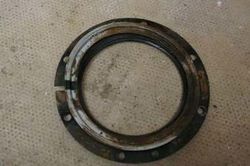
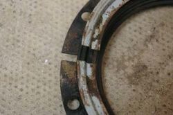
- The confusing part is the order of the seals and rings on the swivel, the picture below is of the correct orientation, note also that the slits in the retainers go to the top.
- Pack the CV with grease (but do not overpack) and re-fit the driveshaft.
- A suitable waterproof grease is available in the BigJimny Shop.
- Grease the new KingPin bearings and insert the top one in the carrier.
- I find the easiest way to grease the bearings is to put them in a polythene bag with some grease and use the bag to squeeze the grease into the bearing, this can be seen in the video. (picture needed here).
- Carefully insert the new bottom bearing and, holding it in place, slide the whole knuckle onto the hub.
- Fill the Knuckle with 100ml of grease, Suzuki recommend only 100ml and not to overfill.
- Now the KingPins need to be inserted, but first they need a bead of sealant around the KingPin.
- Again the BigJimny shop sells suitable sealant.
- Make sure that you have put the correct Kingpin in place.
- Remember you should have marked them when you dismantled them!
- Bolt the Kingpins in and tighten them to the correct torque (18ft/lbs).
- Refit the steering arm (or arms if it is the side with two connections), tightening the nuts to 31ft/lbs.
- Fit the disk and fit the caliper (Caliper bolts 61ft/lbs), brake pads and bolt the caliper down in position (Caliper pin bolt 16/ft/lbs).
- Re-fit the wheel and lower the vehicle.
Torque Settings
Full details of the torque settings can be found in the reference data
Page last edited on 31/01/2017 by user Mlines


