Difference between revisions of "Martins Test"
| Line 38: | Line 38: | ||
=== Removing the shoes === | === Removing the shoes === | ||
| − | [[File:Shoes_lower_spring.jpg|thumb|left|250x250px| | + | [[File:Shoes_lower_spring.jpg|thumb|left|250x250px|Lower spring]] |
| − | + | Use a small pair of pliers and remove the small spring that connects across the base of the brake shoes. | |
<br clear=all> | <br clear=all> | ||
| − | [[File:Shoes_adjuster_spring_2.jpg|thumb|left|250x250px| | + | [[File:Shoes_adjuster_spring_2.jpg|thumb|left|250x250px|Ajuster Spring]] |
| − | + | Use a pair of molegrips to remove the strong spring that joins the top of the shoes with the adjuster. Make a careful note of how the adjuster is fitted, the rod has a forked end and on part of the fork has a step in it. Make careful note of how this fork is fitted. | |
<br clear=all> | <br clear=all> | ||
| − | + | [[File:Shoes_retainer_clip.jpg.jpg|thumb|left|250x250px|Show retainer]] | |
| − | + | Use a pair of pliers and twist the end of the show retaining pin until the spring clip it released | |
| − | [[File:Shoes_retainer_clip.jpg.jpg|thumb|left|250x250px| | ||
| − | |||
<br clear=all> | <br clear=all> | ||
| − | [[File:Shoe_assembly_removal.jpg|thumb|left|250x250px| | + | [[File:Shoe_assembly_removal.jpg|thumb|left|250x250px|Show removal]] |
| − | + | Now the shoes will lift away. Take care not to loose the little adjuster arm and its small spring. | |
<br clear=all> | <br clear=all> | ||
| − | [[File: | + | [[File:Handbrake_cable.jpg|thumb|left|250x250px|Handbrake cable]] |
| − | + | Release the end of the handbrake cable from the arm on the shoe. | |
<br clear=all> | <br clear=all> | ||
Revision as of 19:27, 29 July 2016
Contents
Rear Wheel Bearings
Introduction
The Rear Wheel Bearings on a Jimny can be prone to wearing, particularly when used off-road. The drum brake backing plate is supposed to provide protection for the bearing but it is very poor and you can expect the bearing to fail VERY regularly. Providing you have the correct tools it can be straight forward task.
So what are the symptoms of worn Rear Wheel bearings:
- Grating/Grinding as you rotate a jacked up wheel
- Oil/Grease leaking from rear of drum
- Wheel falling off (yes, really, comes out complete with driveshaft!)
Changing the bearings
Tools
Removing the hub
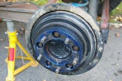
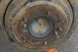
First of all secure the car, release the wheel nuts and jack up the car and remove the road wheel. This then reveals the brake drum, this has a spacer fitted to it. With all the wheel bolts removed AND THE HANDBRAKE OFF the drum can be pulled forward and off the hub.
If the drum is stuck then first of all check that the handbrake is off then insert two small bolts in the holes in the face of the drum. Reach around the back and feel near the top for a rubber bung. Remove the rubber bung and insert a flat bladed screwdriver. Angle the screwdriver so that the blade is pointing to the back of the car and the handle towards the front, you should be able to feel the adjuster wheel. Using the screwdriver turn the adjuster downwards a few clicks. Then gradually tighten the bolts you inserted in the front, the drum should come off.
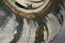
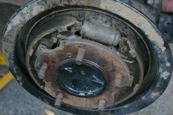
With the drum removed the brake shoes can be seen (covered in mud in this case!). As the hub has to come off to change the bearings you need to remove the brake assembly.
Removing the shoes
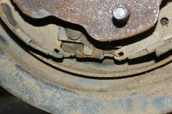
Use a small pair of pliers and remove the small spring that connects across the base of the brake shoes.
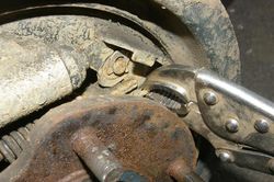
Use a pair of molegrips to remove the strong spring that joins the top of the shoes with the adjuster. Make a careful note of how the adjuster is fitted, the rod has a forked end and on part of the fork has a step in it. Make careful note of how this fork is fitted.
Use a pair of pliers and twist the end of the show retaining pin until the spring clip it released
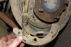
Now the shoes will lift away. Take care not to loose the little adjuster arm and its small spring.
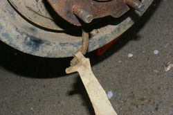
Release the end of the handbrake cable from the arm on the shoe.
Removing the Brake Disc
The caliper is held on with two bolts at the rear (see below).
Release the bolts and tie the caliper to the spring to keep it out of the way.
Now the front brake disc can be removed. If you are lucky it will simply pull off but if you have problems then there are two M8 holes in the disk hub. Simply run two bolts into these holes and the disk will push off the hub. The picture below shows a bolt being used to push the disk off the hub.
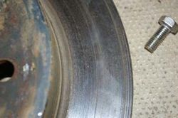
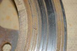
My disk appeared to be ok on the visible side but the rear showed some bad wear so I will change them as part of this job. New disks are available in the BigJimny Store.
Dismantling the Hub
Now the Freewheeling Hub needs to be removed. Suzuki have used Torx bolts to secure these so you will require an E10 socket to remove the bolts.
With the hub removed the driveshaft is exposed. The driveshaft is retained with a circlip so use a pair of circlip pliers to remove it. This is really fiddly and can be an annoying task. Behind the circlip is a rectangular washer that should also be removed. Note that I have also marked with white paint the orientation of the freewheeling hub, this is not strictly needed.
Now for the special tool. The hub is held on by a special round nut that requires a special tool to release it. The outside of the nut is a smooth polished ring which is part of the vacuum seal so it must not be damaged otherwise you will need a new nut(which is exceedingly expensive!). In the centre of the nut, the edge is bent over into a slot to help secure it, the slot can be seen in the above photo in the “2 o’clock” position, use a blade to bend the edge back into line. It is essential that this is completely free otherwise it is impossible to undo the nut and you will break the tool.
This is the tool, it is available from the BigJimny Store. Make sure that the tool and the nut are completely clean as the tool will not fit. Make sure the tool is inserted into the nut correctly with the pins all in the holes in the nut, you are really going to have to swing on the nut to release it. I had to use a long breaker bar AND a piece of scaffold tube. With the nut removed the hub should be removeable, it might need a pull with a slide hammer, mine just pulled off by hand.
With the hub face down on a surface you can now remove the bearing seal from the rear of the hub. I prised mine out with a screwdriver.
Then you can use a pair of long nose pliers to remove the C-Clips that retain the bearing, note that these may be corroded in and difficult to even see at first.
Now comes the first bit that is supposed to be difficult. Suzuki say that the bearing needs to be removed using a press. I decided to have a go myself. Using an old piece of bearing and a steel pin I hammered out the bearing and it only took two or three swift blows. The picture shows the steel pin resting on the bearing before being hit. Note the use of the brake disk to provide a holder for the hub allowing the bearing to be driven out of the bottom.
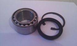
The bearings are Koyo brand as standard. The BigJimny store has a kit available which includes the seal and the c-clips (not all kits contain the c-clips), the Wheel Bearing Kit is here
The rebuild
Suzuki says the new bearing needs to be pressed into place. I decided to try a bit of school boy physics. I coated the bearing in Copper Grease and then put it in the deep freeze overnight.
The hub was placed in the oven at 180 degrees for 30 minutes. So with an ice cold bearing and a very hot hub I put the bearing in the hub, placed the old bearing ring and the steel pin on top and tapped the bearing straight into place. It took two gentle hits!. Again note the use of the brake disk to hold the hub.
ALLOW THE WHOLE ASSEMBLY TO COOL BEFORE TOUCHING OR TURNING THE BEARING ASSEMBLY
Once it is cooled put grease into the ends of the bearing. Then insert the new circlip and the oil seal. I found that the oil seal pressed in ok by hand once coated in Copper Grease. The oil seal has a protruding lip,this must be to the outside of the joint. Grease the inside of the bearing and slide the hub back onto the driveshaft
Grease the hub nut and tighten the nut using the special tool, torque it to 220NM or 160ft lbs – ie. really tight!.
Use a punch to bend the inner lip of the nut to lock it in place. Refit the hub thrust washer and circlip to the driveshaft.
Fit the disk and fit the caliper (Caliper bolts 61ft/lbs), brake pads and bolt the caliper down in position (Caliper pin bolt 16/ft/lbs)
Re-fit the wheel and lower the vehicle.
Torque Settings
Full details of the torque settings can be found in the reference data
Page last edited on 29/07/2016 by user Mlines
