![]() The content of any article might be expanded / improved in the future - revisit it sometimes.
The content of any article might be expanded / improved in the future - revisit it sometimes.
![]() Seen a mistake? Know something that isn't written? Edit and change this article yourself!
Seen a mistake? Know something that isn't written? Edit and change this article yourself!
![]() Some images in the article (if present) can be enlarged by clicking on them.
Some images in the article (if present) can be enlarged by clicking on them.
Contents
Introduction
When supplied from the factory, the transfer box is designed to drive the wheels at speeds appropriate to normal use of the vehicle and standard tyres. Of course, the first thing that an off-roading SJ owner does is to lift the vehicle and fit larger tyres. This immediately ruins the drive ratios and means that the vehicle often struggles to match the performance in terms of speed and power range of a standard factory car.
Therefore, the trick is to change the ratios within the Transfer Box to restore or even improve on the factory performance.
There are a number of ways of doing this:
- Mini Lobster: This conversion applies to 413 owners and Jimny owners only. Simply fit a 410 Transfer Box to a 413/Jimny. The 410 box has lower ratios as standard. This regains some of the performance with a simple exchange.
- Rock Lobster: This conversion takes components of a 410 Transfer Box and components of a 413 box and mixes them together into a 413 case. This provides a low ratio of 4.16 or around 88%. The conversion effectively puts 3rd gear low where 1st gear low was, giving you two further even lower gears. It also changes the ratio of the high box slightly to restore top end performance when on the road. This is the conversion described in this write up.
- Rock Crawler. Using specially machined gears this is available in 1:5 and 1:6 versions. A special conversion that is usually achieved by buying commercial products, can be very expensive.
I first wrote this article in 2005 when I had an SJ and you will find many older versions of this around the Internet, this update has been written now I have a Suzuki Jimny and has been updated after doing a few RockLobster conversions.
Identifying your transfer box
The difficult part of this whole project is successfully identify the 410 Transfer Box. Due to the popularity of lifting SJs, 410 Transfer Boxes are in short supply. If you have a 410 all ready then a 413 box should be cheap to obtain as they are often thrown away.
The simplest method of identifying a box is to know what vehicle it came off.
The problem with SJs is that there are 410s, 413s all of Japanese and Spanish builds. Each type has subtle differences.
- There are some early 410 boxes around. These have small flanges/small shafts and a simpler case. These are NOT suitable for conversion.
- Later 410 boxes have a 4wd switch and a moulding in the casting for a PTO – this is square shaped with a circle in the middle. Also in the middle of the box is a bearing cap with a bolt next to it.
- Put the transfer box into Low Ratio gear and then turn the OUTPUT flange. For one complete turn of the output flange, count the turns on the input flange. If it is a correct 410 box, you will get 2.5 turns (in “clock” turns that’s 2 hours and 30mins). If it is a 413 box, you will get 2.1 turns (in “clock” turns that’s 2 hours and 6 mins).
What is needed
For this conversion you need a 410 Transfer Box and a 413 Transfer Box. You have to destroy the 410 box as part of this process. You will also need access to someone with the skills to re-weld the gears. I found someone willing to perform this task so it is NOT documented fully here.
You will also need a gasket set for a 413 Transfer Box and if you want to do it properly then you should consider replacing the oil seals on the new box.
| Description | OEM part. no. | Alternative source | Comment |
|---|---|---|---|
| Input Shaft Oil Seal | 29971-80050 | 38x60x8 from BearingKing | |
| Input Shaft Front Bearing | 29981-80050 | 62/28 from SimplyBearings | |
| Input Shaft Rear Bearing | 29982-80050 | 63/22 from SimplyBearings | |
| Output Shaft Front Oil Seal | 29971-80050 | 38x60x8 from BearingKing | |
| Output Shaft Rear Oil Seal | 29972-80050 | 38x50x8 from BearingKing | I know this points to the 7mm seal - which fits ok |
| Output Shaft Front Bearing | 08173-63060 | 6306N from SimplyBearings | |
| Output Shaft Rear Bearing | 29981-80050 | 62/28 from SimplyBearings | |
| Output Shaft Rear Bearing Retainer | 29143-80050 | ||
| Front Case Gasket | 29536-80050 | ||
| Centre Case Gasket | 29525-80050 |
When everything is complete, you will need suitable oil for the new shiny Rock Lobster transfer box. Use a (monograde) SAE EP90 transmission oil (that is what Suzuki originally recommended for use in SJ transfer boxes). It should not really matter if it is classified as API GL-4 or GL-5, as there are no "yellow metals" inside the transfer box. If you can't find a monograde SAE 90 oil, then a multigrade SAE 80W-90 oil should also suit OK. It might prove to be slightly less thick, causing a bit increased gear noise from the transfer box.
Required quantity of oil is 1l exactly.
You may also need some shims – you may get some shims from the cases you are breaking up but you may also need to buy some:
| Description | OEM part. no. | Comment |
|---|---|---|
| Output Shaft Shim 0.1 | 29147-80050 | |
| Output Shaft Shim 0.3 | 29148-80050 | |
| Output Shaft Shim 0.5 | 29149-80050 | |
| Input Shaft Shim 0.1 | 29117-80050 | |
| Input Shaft Shim 0.3 | 29118-80050 | |
| Input Shaft Shim 0.5 | 29119-80050 |
Flanges
Another area of much discussion are the input/output flanges.
I have not worked on any system without the handbrake on rear drums. This means that this
information only applies to transfer boxes with the handbrake drum on the transfer box.
I have seen 4 flange types. These are:
| Hole spacing | Flange nut | Flange bolts | Comment |
|---|---|---|---|
| 52 mm | 24 mm | M 8/12 mm head | no good - you have the old small 410 box |
| 52 mm | 27 mm | M 8/12 mm head | OK |
| 55 mm | 27 mm | M 8/12 mm head | OK |
| 60 mm | 27 mm | M 10/14 mm head | OK (most likely this is a 413 box) |
You will need to ensure that you have the correct flange sizes on the new transfer box to match your propeller shafts. They can be swapped over.
The work
Disassembly
- First you have to get both transfer boxes onto the workbench.
- Drain the oil - leave it to drain for a while, you will get oil everywhere anyway!
- Remove the mounting points.
- Remove the gear lever, if this was not done when removing it from the vehicle.
- This is achieved by removing the rubber gaiter and by pressing and rotating the retaining plate.
- Now remove the drum (on drum brake versions) and flanges.
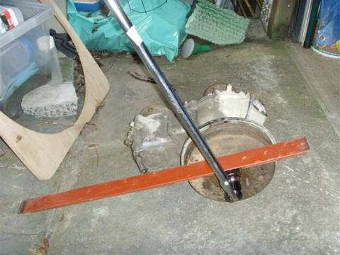
- The flanges are retained by a 27mm nut that is locked on two sides by being bent into grooves in the shaft.
- I have found the best way to remove these nuts is to grind away with a Dremel the bent locking part and then bolt a long metal bar to the flange.
- You can then use a 27mm socket on the nut and use the long metal bar to prevent the flange from rotating.
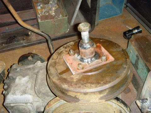
- The Drum Brake also needs removing.
- This can be difficult.
- I found that by completely undoing the nuts on the adjuster mechanism on the rear that the brake mechanism fell apart and the drum could be easily removed with a slide hammer.
- Andy also had problems with his and he created a puller from some metal plate and a bolt.
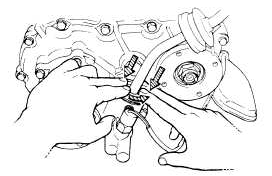
- Now remove the speedometer driven gear.
- This is the mount where the speedo cable was attached.
- Make sure the little 10 mm bolt is fully removed.
- You may be lucky and be able to pull out the gear with mole grips.
- But it may have corroded into place in which case you are in trouble.
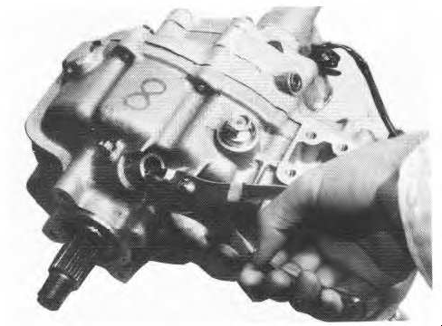
- I found that by grinding (with the Dremel) a small groove in the top of the gear and then insert a small chisel in the groove and gently hit the gear attempting to rotate it and break the corrosion.
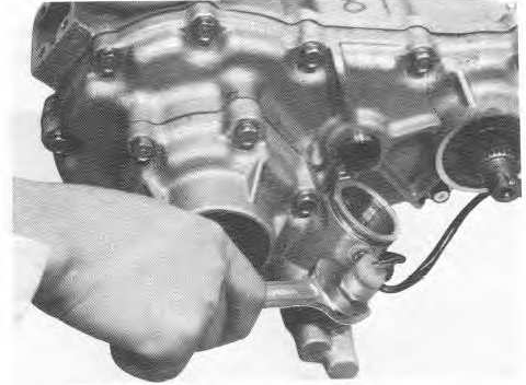
- This picture is not clear, the transfer case is upside down, the speedo drive is just below the painted number 8 on the picture.
- Now remove the 4wd switch.
- This has a small ball bearing inside - do not loose this!
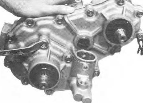
- Now take off the front section of the transfer case.
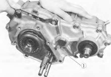
- Now undo the bolts that hold the centre and rear cases together.
- Do not undo the bolt marked "1" in the picture.
- When you split the cases, be careful of the shims that will fall off the shafts.
- Make a note of where the shims came from.
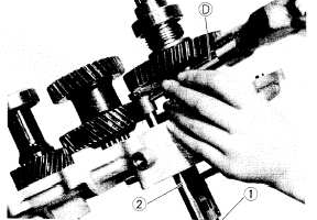
- Using a pin driver (or old nail!), drive out the pin on the shift fork on the main gear side of the transfer box.
- This is the pin holding the fork on the end of the shift shaft.
- Note that it will hit the intermediate gear if the selector shaft is not in the correct position.
- However if this is the case, it is still possible to “bend” it out.
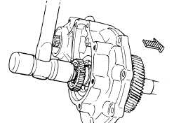
- At this point you will be able to tap the output shaft out of the case.
- Note that this sketch shows a total strip.
- Therefore both shifter shafts have been removed in the sketch - this is NOT necessary.
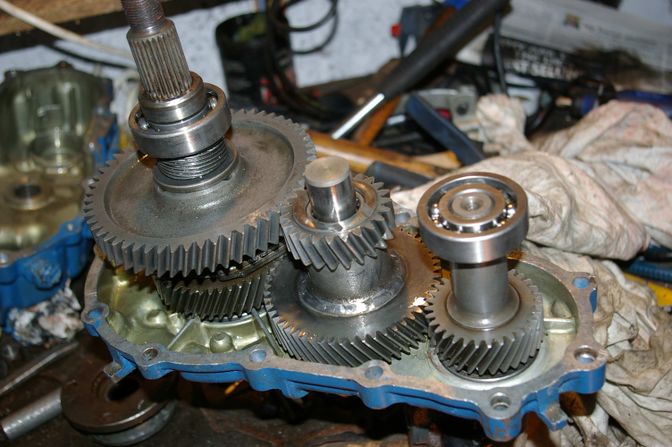
- The intermediate shaft is now free to be removed.
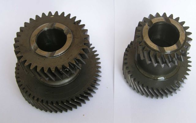
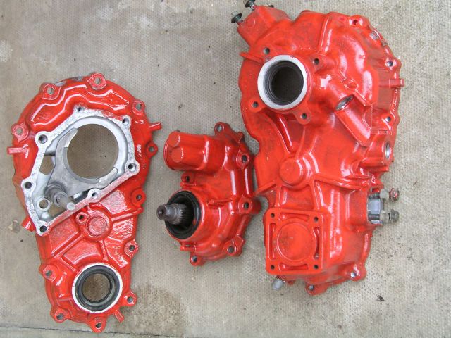
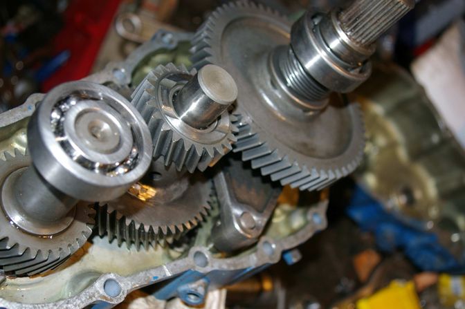
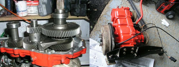
- Once you have disassembled both you should have the gears as in this picture.
Modifications
- Now is the time to get the intermediate gears cut and welded.
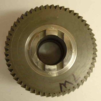
- You need to connect the larger gear on the 410 to the smaller gear on the 413.
- As I said previously I got someone else to do this bit.
- Whilst the gears are off being cut and shut you can busy yourself preparing the rest of the box.
- A coat of paint will not go amiss, and a lobster can only be RED! (unless its Blue – I changed colour the second time around).
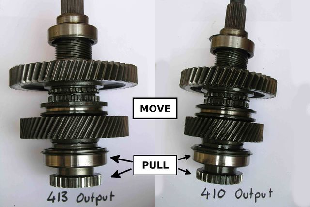
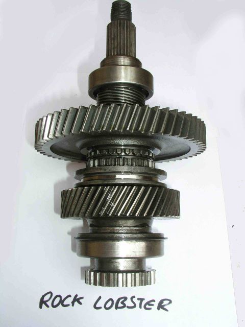
- You also need to combine the gears from the 410 output shaft and the 413 output shaft to create a new Rock Lobster output shaft.
- Take the 413 output shaft and remove the spring clip from the gear shown at the bottom of the picture.
- Be aware that there is a small needle bearing inside the end of the shaft.
- Be careful NOT to rest the end of the gear puller on this bearing as it will push it in or even break it.
- Pull this gear off, then pull off the bearing (also the one at the bottom of the picture).
- Repeat for the 410 shaft.
- Put the gear from the 410 shaft onto the 413 shaft and press on the bearing and the end gear, replacing the spring clip.
- You should end up with the gears shown in the picture.
- By now you should have also built your replacement intermediate gear.
- The manufacturer of my gear used pins along the gear shear line to reinforce the joint.
- This picture shows the gears before welding.
- This picture shows the welded gears.
Rebuild
- Now the rebuild begins.
- If this was the Haynes manual it would tell you to reverse the above procedure, but there is more to it than that.
- If you are changing the bearings you need to pull out the old bearings and push on the new.
- The bearing types are given in the table earlier in this document.
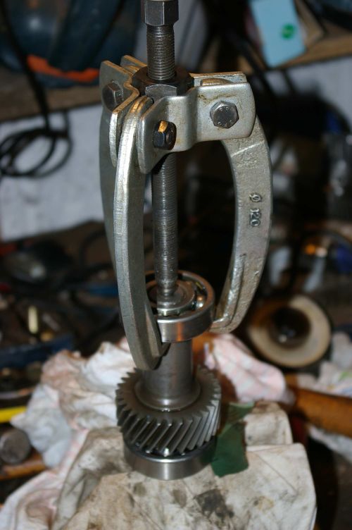
- The output shaft bearings are simply pulled off the shaft.
- This picture shows a cheap bearing pulling being put to use.
- Putting the bearings back on requires some care.
- They can be pressed or driven on, but also if you use some ingenuity you can use the threads and flanges to push them into place.
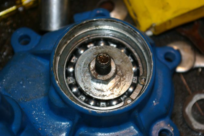
- The front case bearing is more hidden.
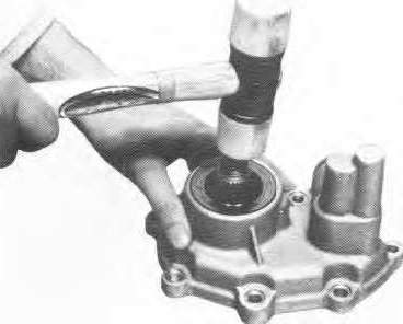
- You need to pull out the oil seal and remove the large circlip inside.
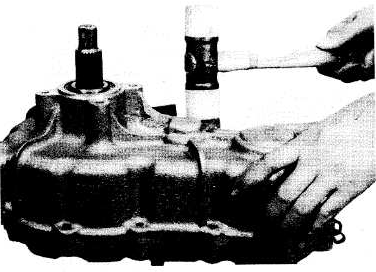
- Using a soft mallet you can then drive out the shaft.
- It will then be possible to drive the old bearing out from behind.
- Putting the new bearing in requires some care.
- I used a metal plate behind the case and put a bolt through with some large washers and tightened the bolt, pulling the bearing into position.
- At this point, with all the bearings changed, you can fit new oil seals if required.
- Now to re-assemble the gearsets.
- The factory manual spends a lot of time discussing “end float” and how it should be set correctly.
- The variation is given as being between 0.15 and 0.25 mm, which is very difficult to measure given the long mathematical addition given in the manual.
- After much trial and error I found it was not possible to measure this.
- However, Richard Wattam told me a sneaky technique.
- This involves a bit of work assembling and dismantling the case, but it works.
- First of all insert the input shaft on its own.
- Assemble (and bolt together) the case WITHOUT a gasket and check how the shaft turns.
- If it is stiff then it is fine and no shims are needed.
- If it turns freely then disassemble and add a shim.
- Rebuild the case and see if the shaft becomes stiff to turn.
- Once it does then it is correctly shimmed.
- Now you can move on to the output shaft.
- Again, repeat the process with only the output shaft and WITHOUT the gasket.
- Keeping adding shims until the output shaft is stiff to turn.
- This process works because you have not fitted the gasket.
- Once it is fitted it adds the correct spacing!
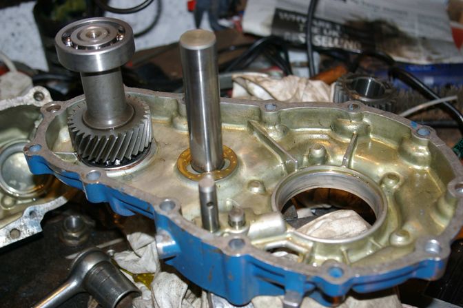
- First build the input Shaft onto the middle case section.
- I found the input shaft difficult to insert.
- In the end I refitted the flange and tightened the flange nut to pull the gearset into position.
- Then fit the intermediate shaft and finally the output shaft.
- Remember to include the shift fork as you put the output shaft in place.
- There is not enough room to add it afterwards!
- Now the two cases can be recombined.
- Hopefully you have cleaned the mating surfaces up already when you were checking the end float.
- Make sure that the gaskets, shims and thrust bearings are all in place.
- You may need to persuade them to stay put with a dab of silicon gasket.
- Squirt some gearbox oil over the bearings and moving parts to help everything when it spins up for the first time.
- The cases should then push together with a firm push.
- Bolt on the front case section.
- Reinsert the 4WD switch and ball bearing.
- If you are building the Transfer Case for an SJ you will need to reinsert the speedometer drive at this point.
- If you are building it for a Jimny, then you will have no need for the mechanical drive.
- However you will need to put something in to stop it leaking oil.
- I simply took the SJ speedo mount and welded up the end and silicon gasket sealed it into place.
- The left picture shows the starting point and the right picture shows my blob welding part way through (I cleaned it up with an angle grinder so I could spot the holes).
- Now replace the flanges and drum brake assembly (if required).
- Stand back and admire your work.
End of the guide.
Page last edited on 20/12/2019 by user Mlines

