Difference between revisions of "ABS System - Reading and Clearing Fault codes"
Tag: visualeditor |
m (Category adjustment) |
||
| (8 intermediate revisions by 2 users not shown) | |||
| Line 1: | Line 1: | ||
| − | + | {{intro-notes}} | |
| + | |||
== Introduction == | == Introduction == | ||
| − | |||
| − | This is achieved by shorting out pins on a small connector located behind the dashboard. It is on the drivers side (both for Right Hand Drive and Left Hand Drive) behind the steering wheel, on the side of the steering wheel nearest the door. Therefore on vehicles with the steering wheel on the proper side (RHD) it is behind the dashboard behind the drivers right hand when it is holding the steering wheel. If you are in one of those Jimnys with the steering wheel on the wrong side (a legacy of being invaded by Napoleon) then it is behind the dashboard behind the drivers left hand when it is holding the steering wheel. | + | |
| + | When the ABS system detects a fault, it lights a lamp on the dashboard. This means the controller has detected an issue and is highlighting it for attention. | ||
| + | |||
| + | In common with a lot of manufacturers, Suzuki expects you to return the vehicle to a dealer to get the problem diagnosed. Dealers subscribe to an expense proprietary code reader system to read the codes and it becomes an expensive process to find out what is wrong. | ||
| + | |||
| + | However, international regulations make it mandatory that non-Suzuki aligned garages can also carry out diagnosis, therefore Suzuki provides a manual way of getting the error codes out of the controller. | ||
| + | |||
| + | |||
| + | == Preparing the read-out == | ||
| + | |||
| + | |||
| + | The read-out of the error codes from the ABS computer is achieved by shorting out pins on a small connector located behind the dashboard. It is on the drivers side (both for Right Hand Drive and Left Hand Drive) behind the steering wheel, on the side of the steering wheel nearest the door. | ||
| + | |||
| + | Therefore, on vehicles with the steering wheel on the proper side (RHD) it is behind the dashboard behind the drivers right hand when it is holding the steering wheel. | ||
| + | |||
| + | If you are in one of those Jimnys with the steering wheel on the wrong side (a legacy of being invaded by Napoleon) then it is behind the dashboard behind the drivers left hand when it is holding the steering wheel. | ||
| + | |||
It is a Blue colour connector with a PINK wire (with black stripe) and a Black wire and SIX connector positions but only two in use. | It is a Blue colour connector with a PINK wire (with black stripe) and a Black wire and SIX connector positions but only two in use. | ||
| − | == Reading codes == | + | |
| + | <gallery widths="320px" heights="320px" class=center> | ||
| + | File:Suzuki Jimny - blue 6-pin ABS diagnostic connector with pink wire with black stripe under dash board - A01.jpg|Blue ABS diagnostic connector location | ||
| + | File:Suzuki Jimny - blue 6-pin ABS diagnostic connector with pink wire with black stripe under dash board - B01.jpg|Blue ABS diagnostic connector pinout appearance | ||
| + | File:Suzuki Jimny - ABS diagnostic connector pinout sketch - A01.jpg|ABS diagnostic connector pinout sketch | ||
| + | </gallery> | ||
| + | |||
| + | |||
| + | == Reading the codes == | ||
| + | |||
| + | |||
To read the codes: | To read the codes: | ||
| − | # | + | # Drive the vehicle at over 30 mph for at least 1 minute. |
| − | # Stop, switch off ignition | + | # Stop, switch off ignition. |
| − | # Using a piece of wire, short the two pins in the connector together | + | # Using a piece of wire, short the two pins in the connector together. |
| − | #* ''Variation: Early models (G13BB)require you to remove the ABS | + | #* ''Variation: Early models (with G13BB engine) require you to remove the ABS diode (pull it out) at this point, this is not shown in the picture (does anyone have a picture of the diode??)'' |
| − | # Turn on the ignition | + | # Turn on the ignition. |
| − | The ABS light will now flash a code to tell you the fault, the flashing repeats itself | + | |
| + | The ABS light will now flash a code to tell you the fault, the flashing repeats itself. | ||
The code is a two digit code so will flash the first digit, pause for 1 second and then flash the second digit, then after a 3 second delay it will repeat. | The code is a two digit code so will flash the first digit, pause for 1 second and then flash the second digit, then after a 3 second delay it will repeat. | ||
| + | |||
| + | {{note|If more than one code is stored, then all the codes will sequence through}} | ||
| + | |||
The codes are: | The codes are: | ||
| Line 76: | Line 106: | ||
|ABS control module | |ABS control module | ||
|} | |} | ||
| + | |||
| + | Once complete, remove the wire. | ||
| + | |||
| + | {{note|Don't forget to return the diode back into position if you removed it !}} | ||
| + | |||
== Clearing codes == | == Clearing codes == | ||
| + | |||
| + | |||
To clear the codes: | To clear the codes: | ||
| − | # Switch off ignition | + | # Switch off ignition. |
| − | # Using a piece of wire, short the two pins in the connector together | + | # Using a piece of wire, short the two pins in the connector together. |
| − | # Turn on the ignition | + | # Turn on the ignition. |
| − | # Pull and | + | # Pull and remake the wire link at least 5 times within a 10 second period. |
| − | # Turn off ignition and remove wire | + | # Turn off ignition and remove the wire. |
| − | + | ||
| + | |||
| + | To be certain that the clearing has been successfully performed, you can repeat the "reading the codes" procedure above to confirm that the code is now "12" = ''normal''. | ||
| + | |||
| + | |||
| + | {{Edited}} | ||
| + | |||
| + | [[Category:Howto - gen3]] | ||
| + | [[Category:Brakes - gen3]] | ||
Latest revision as of 13:23, 21 February 2019
![]() The content of any article might be expanded / improved in the future - revisit it sometimes.
The content of any article might be expanded / improved in the future - revisit it sometimes.
![]() Seen a mistake? Know something that isn't written? Edit and change this article yourself!
Seen a mistake? Know something that isn't written? Edit and change this article yourself!
![]() Some images in the article (if present) can be enlarged by clicking on them.
Some images in the article (if present) can be enlarged by clicking on them.
Introduction
When the ABS system detects a fault, it lights a lamp on the dashboard. This means the controller has detected an issue and is highlighting it for attention.
In common with a lot of manufacturers, Suzuki expects you to return the vehicle to a dealer to get the problem diagnosed. Dealers subscribe to an expense proprietary code reader system to read the codes and it becomes an expensive process to find out what is wrong.
However, international regulations make it mandatory that non-Suzuki aligned garages can also carry out diagnosis, therefore Suzuki provides a manual way of getting the error codes out of the controller.
Preparing the read-out
The read-out of the error codes from the ABS computer is achieved by shorting out pins on a small connector located behind the dashboard. It is on the drivers side (both for Right Hand Drive and Left Hand Drive) behind the steering wheel, on the side of the steering wheel nearest the door.
Therefore, on vehicles with the steering wheel on the proper side (RHD) it is behind the dashboard behind the drivers right hand when it is holding the steering wheel.
If you are in one of those Jimnys with the steering wheel on the wrong side (a legacy of being invaded by Napoleon) then it is behind the dashboard behind the drivers left hand when it is holding the steering wheel.
It is a Blue colour connector with a PINK wire (with black stripe) and a Black wire and SIX connector positions but only two in use.
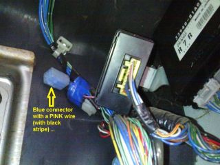
Blue ABS diagnostic connector location
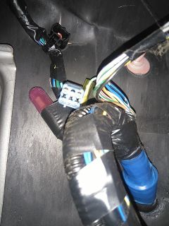
Blue ABS diagnostic connector pinout appearance

ABS diagnostic connector pinout sketch


Reading the codes
To read the codes:
- Drive the vehicle at over 30 mph for at least 1 minute.
- Stop, switch off ignition.
- Using a piece of wire, short the two pins in the connector together.
- Variation: Early models (with G13BB engine) require you to remove the ABS diode (pull it out) at this point, this is not shown in the picture (does anyone have a picture of the diode??)
- Turn on the ignition.
The ABS light will now flash a code to tell you the fault, the flashing repeats itself.
The code is a two digit code so will flash the first digit, pause for 1 second and then flash the second digit, then after a 3 second delay it will repeat.
![]() If more than one code is stored, then all the codes will sequence through
If more than one code is stored, then all the codes will sequence through
The codes are:
| Code | Reason |
|---|---|
| 12 | Normal |
| 15 | G sensor circuit fault |
| 16 | Stop lamp switch circuit fault |
| 21 or 22 | Righthand Front sensor fault |
| 25 or 26 | Lefthand Front sensor fault |
| 31 or 32 | Righthand Rear sensor fault |
| 35 or 36 | Lefthand Rear sensor fault |
| 41 | Right front Hold solenoid valve |
| 42 | Right front Release solenoid valve |
| 45 | Left front Hold solenoid valve |
| 46 | Left front Release solenoid valve |
| 55 | Rear Hold solenoid valve |
| 56 | Rear Release solenoid valve |
| 57 | Power source issue |
| 61 | ABS Pump motor circuit |
| 63 | ABS Solenoid valve circuit |
| 71 | ABS control module |
Once complete, remove the wire.
![]() Don't forget to return the diode back into position if you removed it !
Don't forget to return the diode back into position if you removed it !
Clearing codes
To clear the codes:
- Switch off ignition.
- Using a piece of wire, short the two pins in the connector together.
- Turn on the ignition.
- Pull and remake the wire link at least 5 times within a 10 second period.
- Turn off ignition and remove the wire.
To be certain that the clearing has been successfully performed, you can repeat the "reading the codes" procedure above to confirm that the code is now "12" = normal.
Page last edited on 21/02/2019 by user Bosanek